
DC-DC converters are widely utilized across applications ranging from consumer electronics to heavy-duty industrial and railway systems. While they ensure precise voltage delivery to various loads, power dissipation is an inevitable reality in switching power supplies—stemming primarily from conduction losses, switching losses, and magnetic core losses.
If left unmanaged, this accumulated heat can degrade electrical performance, drastically shorten the converter’s operating lifespan, or induce catastrophic thermal failure. Consequently, robust thermal management is a cornerstone of reliable power system design.
The following sections examine the internal heat generation mechanisms, key influencing factors, and proven thermal design strategies engineers employ to maintain optimal operating temperatures.
Thermal Management in DC-DC Converters: The Role of Junction Temperature
In DC-DC converters, heat is primarily generated by active power semiconductors (such as MOSFETs and diodes) and passive magnetic components (such as inductors and transformers). For semiconductors, thermal energy originates directly at the internal semiconductor junctions (p-n junctions or channels), where current density and switching activity are concentrated. The term junction temperature (TJ) refers to the operating temperature of these critical internal regions.
Junction temperature represents the temperature of the hottest spots within power semiconductors and serves as the most critical indicator of a converter’s thermal performance and long-term reliability. If TJ exceeds safe operational limits, semiconductor performance degrades, leakage currents increase, and the physical lifespan of the device is drastically shortened due to thermal stress.
Consequently, advanced thermal management strategies—such as internal thermal potting, optimized PCB thermal vias, external heat sinks, or forced convection—are fundamentally engineered to efficiently extract heat and keep junction temperatures well within safe, manufacturer-specified margins.
The Thermal Equation: What Contributes to Junction Temperature?
To manage heat effectively in a DC-DC converter, it is essential to understand what drives the junction temperature upward. The fundamental relationship between junction temperature, ambient temperature, and power dissipation is expressed as:
TJ = TA + (PD × θJA)
- TJ (Junction temperature): The internal operating temperature of the semiconductor junction.
- TA (Ambient temperature): The temperature of the surrounding environment.
- PD (Power dissipation): The total power lost as heat during device operation.
- θJA (Thermal resistance): A measure of how much the component resists the heat flow from its internal junction to the surrounding air. A lower value indicates superior heat dissipation capability.
This formula clearly demonstrates that junction temperature rises when either more heat is generated (PD↑) or when heat cannot escape efficiently (θJA↑). Consequently, thermal design strategies focus on two fundamental principles:
- Reducing power dissipation (PD↓) to minimize the total amount of heat generated at the source.
- Enhancing heat flow by lowering thermal resistance (θJA↓) to improve how efficiently thermal energy is carried away from the components.
DC-DC Converter Design to Reduce PD: Lowering Heat Generation
Power dissipation (PD) represents the portion of input power that does not reach the output, converting into heat instead of useful work. We begin with the fundamental efficiency formula:
η = POUT / PIN
In this equation, η represents efficiency, defined as the ratio of output power to input power. Ideally, η should approach 1 (or 100%), minimizing energy lost as heat. Separately, power dissipation can be expressed as:
PD = PIN − POUT
By combining both equations, PD can be expressed directly in terms of output power and efficiency:
PD = POUT (1/η − 1)
This mathematical relationship demonstrates a vital rule: the higher the efficiency (η↑), the lower the heat generated (PD↓). Consequently, improving conversion efficiency is the most effective approach to reducing power dissipation.
Key strategies for improving efficiency include:
1. Use High-Efficiency Components
Select components featuring low conduction resistance (such as MOSFETs with low RDS(on)), minimal switching losses, and high-quality passives (such as capacitors and inductors with low Equivalent Series Resistance, ESR) to curb internal energy loss.
2. Reduce Energy Loss During Switching
Each switching transition creates a transient period where both voltage and current overlap at high values, serving as a primary source of heat generation. Employing fast-switching power transistors and minimizing parasitic elements (such as stray capacitance and inductance) helps shorten transition durations and reduce switching-cycle energy waste.
3. Optimize Circuit Layout
A well-engineered PCB layout prevents localized hot spots and optimizes both electrical current flow and thermal paths. Key layout practices include:
- Utilizing wider copper planes to spread thermal energy evenly.
- Incorporating thermal vias to conduct heat efficiently to inner or bottom layers.
- Mounting heat-prone components directly to metal chassis or heatsinks to facilitate conduction and prevent the "oven effect."
For an ideal choice of a well-designed circuit layout that delivers exceptional efficiency, the MINMAX MRZI100 series is engineered to handle demanding thermal and electrical environments.
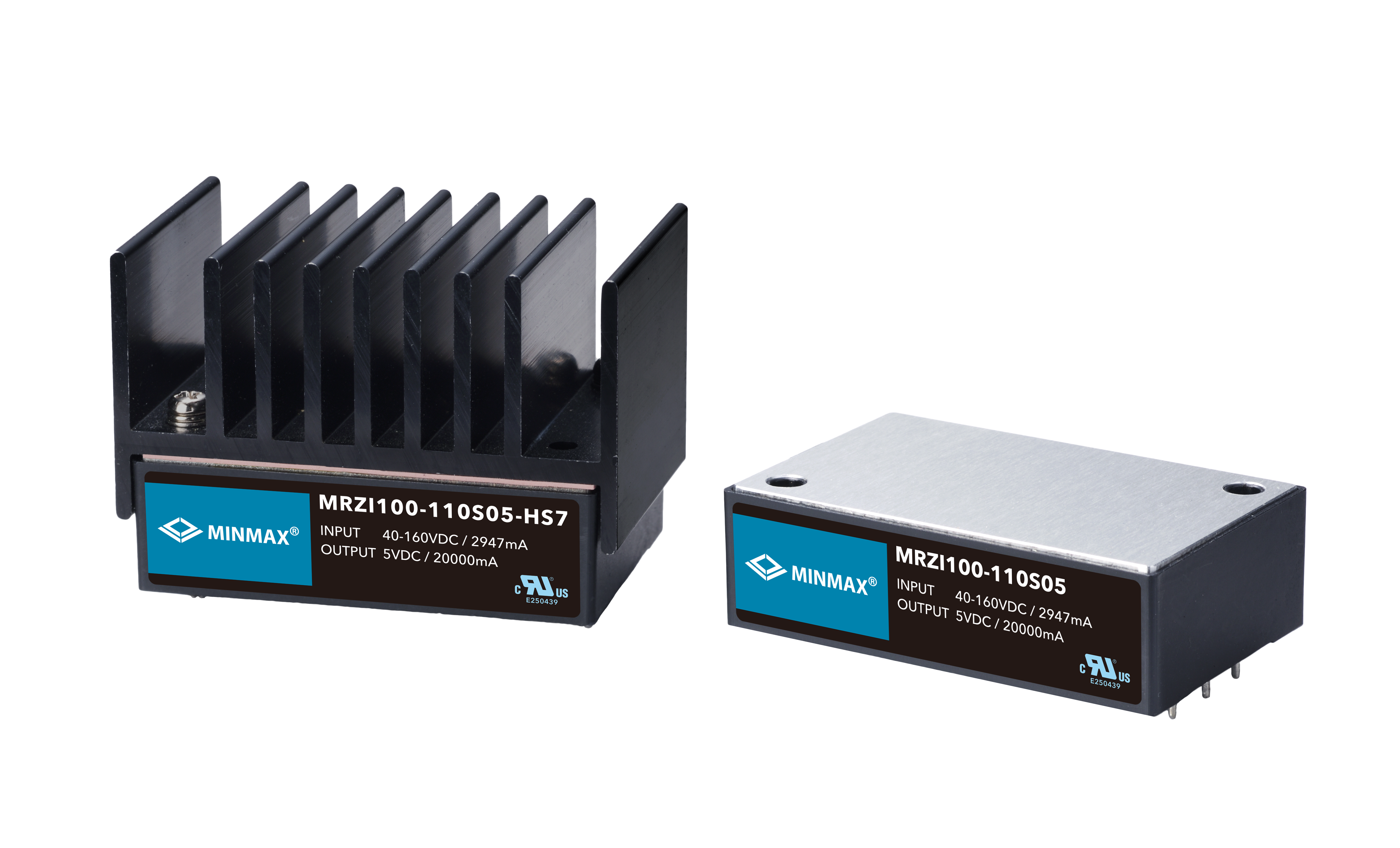
Each of these design decisions collectively improves overall converter efficiency, resulting in a lower PD, superior thermal performance, and enhanced power supply reliability.
DC-DC Converter Design to Reduce θJA: Enhancing Heat Dissipation
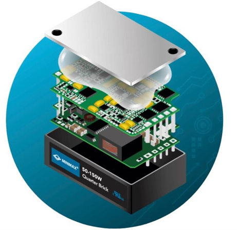
Even in highly optimized designs, no converter is 100% efficient—some energy will always be lost as heat. That’s why, after minimizing power dissipation (PD), the next critical step is to focus on removing the generated heat. This is where thermal resistance, expressed as θJA, becomes critical.
θJA represents the total thermal resistance from the component’s junction to the surrounding air. A lower value means better heat flow and easier cooling. It is typically broken down into two main segments:
| Thermal Resistance Parameter | Definition & Impact |
|---|---|
| θJC (Junction-to-Case Thermal Resistance) | The internal thermal resistance from the semiconductor die junction to the outer package or case of the component. This path is largely fixed by the physical packaging and internal material selection determined by the manufacturer. |
| θCA (Case-to-Ambient Thermal Resistance) | The external thermal resistance from the component's case through any thermal interface materials (TIM), PCB copper planes, attached heat sinks, and into the surrounding air. This is the domain where thermal management solutions, such as heatsinks and airflow, are actively applied. |
Together, they form the total thermal resistance:
θJA = θJC + θCA
Lowering θJA improves cooling efficiency and ensures that the junction temperature remains strictly within safe operating limits. Key strategies to reduce θJA include:
1. Optimize PCB Layout for Thermal Relief
Utilize wide copper planes to spread heat efficiently. Add thermal vias between PCB layers to transfer heat vertically away from top-layer components. Place heat-generating elements strategically to avoid centralized hotspots.
2. Use High Thermal Conductivity Materials
Apply metal casings, thermal interface materials (TIMs), and heat-spreading baseplates to significantly improve thermal conduction away from primary heat sources.
3. Implement Active or Passive Cooling
Depending on the application's constraints, add an external heatsink (passive cooling) or incorporate a fan for forced convection (active cooling) to substantially boost convective heat dissipation.
The MINMAX MRZI150 series stands out with its high thermal conductivity casing, optimized PCB layout, and optional heatsinks. These thermal enhancements allow the converter to operate reliably across a wide operating temperature range of -40°C to +105°C, even in demanding railway environments.
Conclusion
Effective thermal management serves as the absolute backbone of ensuring DC-DC converter reliability, efficiency, and safety. From minimizing power loss at the component level to enhancing macroscopic heat dissipation, every design choice directly impacts long-term operational stability.
MINMAX offers high-efficiency DC-DC converters engineered for demanding environments, featuring robust thermal designs, wide operating temperature ranges, and reinforced insulation.
Contact us to find the best-fit solution for your power system architecture.