Contents
1. What Is an Isolated DC-DC Converter? Principles, Benefits, and Typical Use Cases
2. Isolated DC-DC Converter Use Examples in Different Circuit Types
3. Typical Application Areas for Isolated DC-DC Converters
4. What Is a Non-Isolated DC-DC Converter? Topologies, Advantages, and Typical Use Cases
5. Isolated vs. Non-Isolated DC-DC Converters: Key Differences
6. When to Choose an Isolated DC-DC Converter
7. When to Choose a Non-Isolated DC-DC Converter
8. Conclusion: Selection Guidelines and Common Power Architecture
The key difference between isolated and non-isolated DC-DC converters is whether the input and output circuits are electrically separated by galvanic isolation. Isolated converters use transformers or coupling components to create a safety boundary and suppress noise, while non-isolated converters share a common ground and prioritize efficiency, size, and cost.
DC-DC converters play a critical role in modern electronic products by converting direct current (DC) from one voltage level to another. This function is essential for systems that contain multiple circuits with different voltage requirements, ensuring optimal performance and efficiency.
The distinction between isolated and non-isolated DC-DC converters is particularly important. The fundamental difference lies in whether there is galvanic isolation between the input and output. Isolated converters transfer energy through transformers or coupling components, breaking the direct DC conduction path. This creates an electrical safety boundary, suppresses ground loops, and reduces both differential-mode and common-mode noise.
Non-isolated converters, on the other hand, share a common ground with the system. They offer higher efficiency, smaller size, and lower cost, making them ideal for point-of-load (POL) power delivery close to the load.
Because this choice affects system safety, size, cost, and efficiency, engineers and designers must clearly understand these differences in order to select the most suitable converter for a given application. The following sections provide a detailed discussion.
What Is an Isolated DC-DC Converter? Principles, Benefits, and Typical Use Cases
An isolated DC-DC converter provides galvanic isolation, meaning that the input side (primary side) and output side (secondary side) are electrically independent and have no direct conductive path between them. This prevents direct energy flow and eliminates common-ground interference.
Although there is no direct electrical connection, energy can still be transferred through an isolation transformer, as shown in Figures 3 and 4. On the primary side, electrical energy is converted into magnetic energy, which is then transferred to the secondary side and converted back into electrical energy to supply the load.
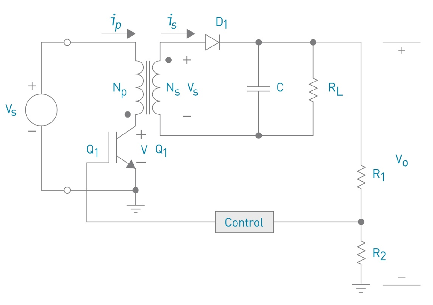
To maintain stable output regulation under isolated conditions, control signals are transmitted via isolation components such as optocouplers, as shown in Figure 3. Figure 4 illustrates a typical circuit architecture: the primary-side switching stage drives the transformer, the secondary side rectifies and filters the output, and feedback is provided to the control circuit for regulation.
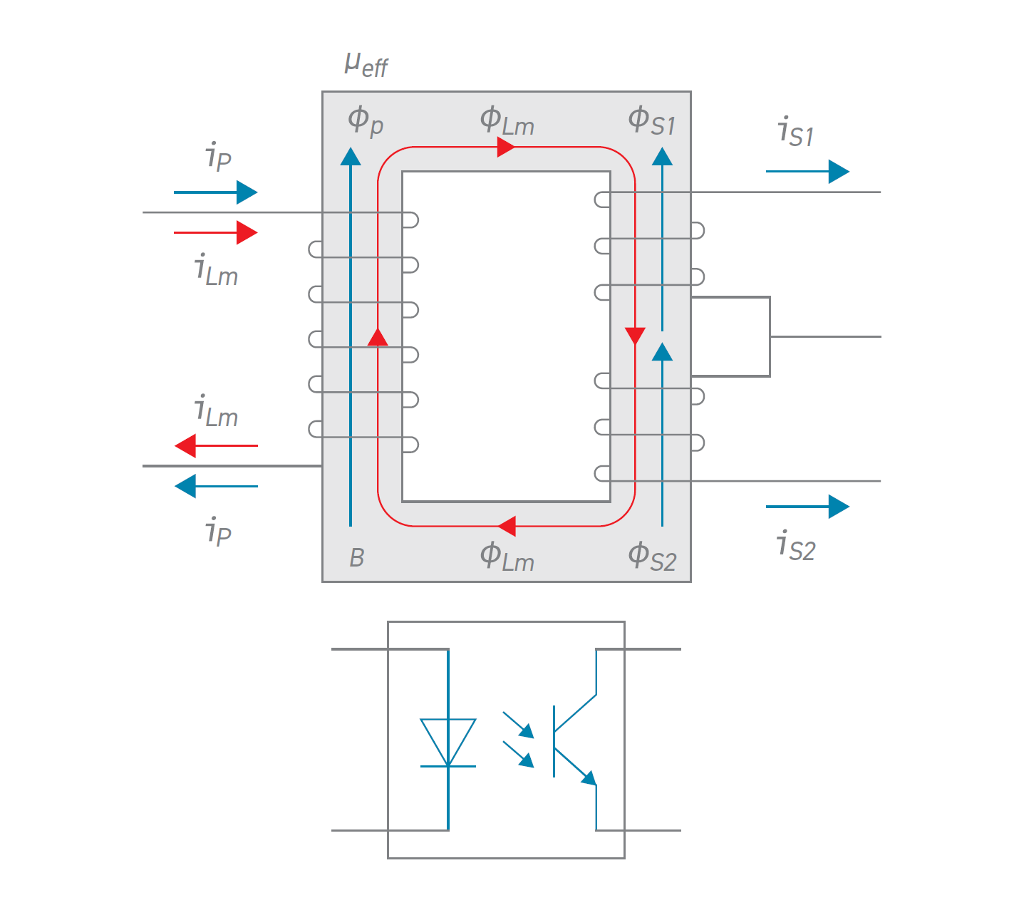
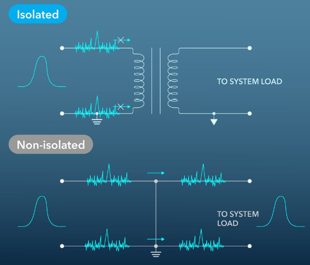
Figure 3. Galvanic Isolation and Energy/Signal Transfer in an Isolated DC-DC Converter
Key Advantages of Isolated DC-DC Converters
Electrical Safety
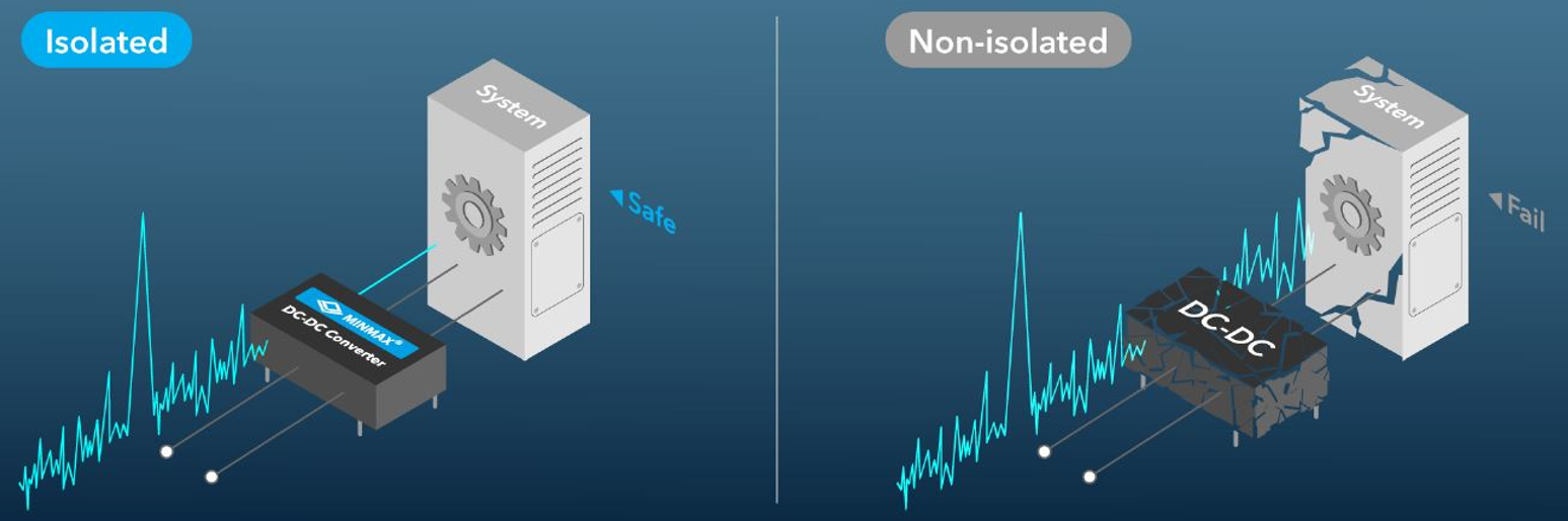
As shown in Figure 5, transformers or optocouplers create an electrical isolation barrier between the input and output, effectively preventing high differential voltages on the primary side from reaching the secondary side. This protects low-voltage components and operators, which is especially critical in applications that must comply with safety standards such as IEC 60601-1 and IEC 62368-1.
Noise Suppression and Ground Loop Elimination
As illustrated in Figure 6, galvanic isolation effectively blocks differential-mode noise circulating between positive and negative rails, as well as common-mode noise caused by ground potential differences between system blocks. By eliminating ground loops—especially in low-frequency ranges—isolated DC-DC converters improve signal stability and system reliability while preventing leakage currents from flowing through unintended paths.
Isolated DC-DC Converter Use Examples in Different Circuit Types
Examples of Isolated DC-DC Converters in Different Circuit Applications:
Noise Sources: High di/dt switching currents and parasitic capacitances generate high-frequency common-mode currents; large current loops may carry noise into sensitive areas.
Isolation Benefits:
- • Breaks DC reference paths to eliminate ground loops
- • Confines noise to the primary side, reducing system-wide coupling
Noise Sources: High-speed logic (MCU/FPGA/SerDes/DDR) causes ground bounce and EMI if return paths cross domains.
Isolation Benefits:
- • Limits digital return currents to local domains
- • Prevents ground potential differences from injecting noise or surge currents via communication lines
Noise Sources: Sensors, amplifiers, and ADCs are highly sensitive to ground noise and common-mode disturbances.
Isolation Benefits:
- • Separates measurement front ends from system ground
- • Improves measurement accuracy when combined with isolated amplifiers or ADCs
Isolated DC-DC Converter Application Examples
Case Study 1:
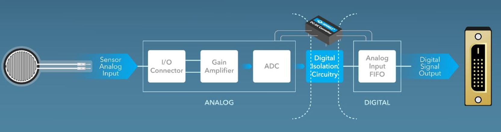
As shown in Figure 7, continuous analog signals from sensors must be amplified and converted into digital data by an ADC. When analog and digital circuits share the same ground, ground potential differences and return path impedance can introduce noise, leading to conversion errors and signal degradation.
By introducing digital isolation circuitry and powering the isolated domain with an isolated DC-DC converter, the system:
- • Blocks noise coupling between analog and digital grounds
- • Prevents transient voltages from reaching digital controllers
- • Ensures signal accuracy and stability
Case Study 2:
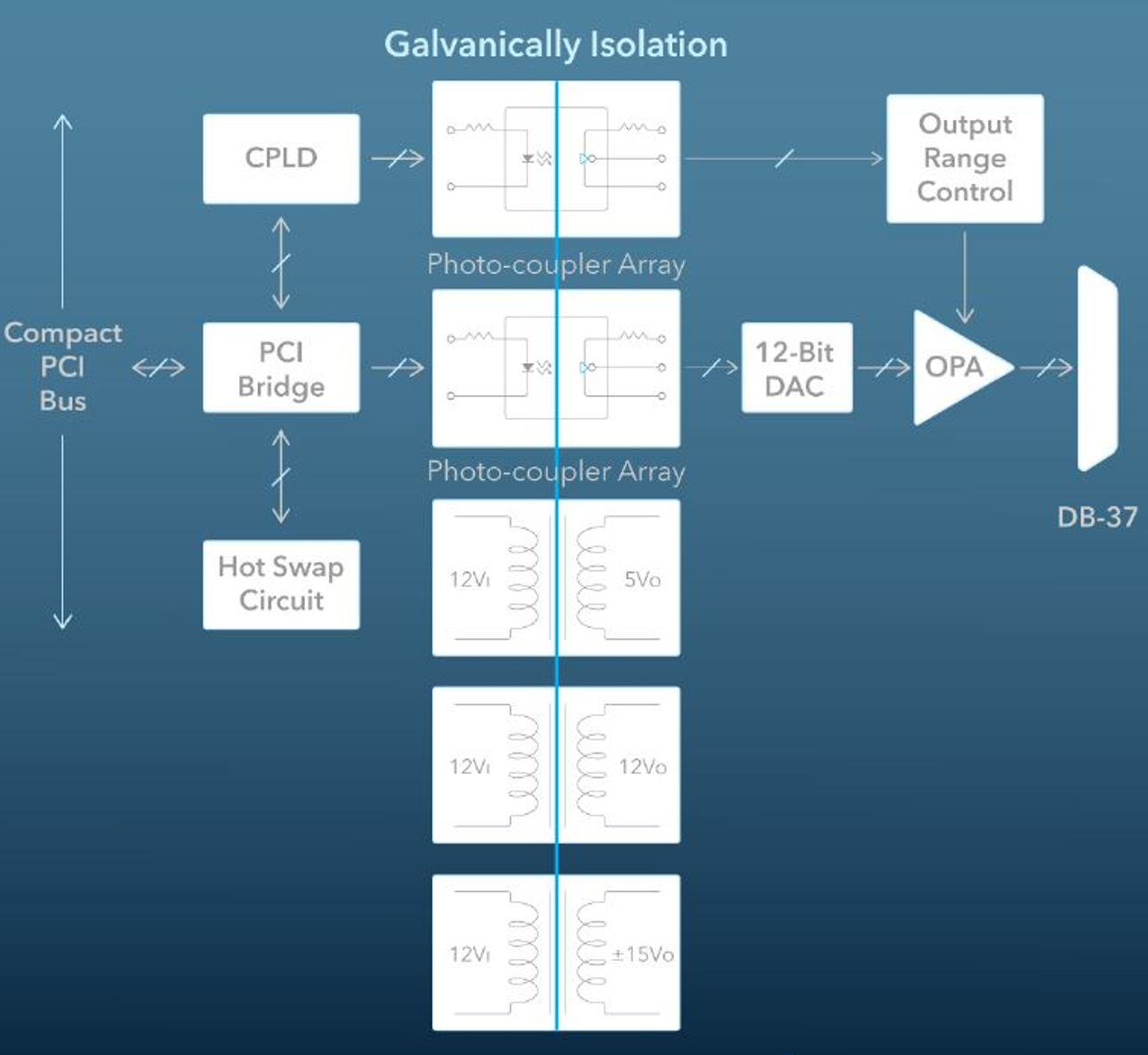
As shown in Figure 8, a CompactPCI-based system uses isolated DC-DC converters and optocoupler arrays to ensure electrical safety and signal integrity across multiple functional modules. Isolated power rails supply 5 V, ±12 V, and ±15 V independently, preventing interference between analog, digital, and communication circuits.
The overall design logic is as follows:
- • Communication Layer: During transmission via serial communication buses (RS-232, RS-485, CAN, etc.), each module is typically powered by different power supplies, and the physical distance is relatively long, easily leading to ground potential differences. Isolated DC-DC converters can cut off the common ground path, preventing common-mode noise currents in the ground loop from causing communication interference or equipment damage.
- • Power Supply Layer: In the illustration, the 12V input is converted into multiple independent power supplies (5V, ±12V, ±15V, etc.) by multiple isolated DC-DC converters, each powering a different subsystem, ensuring that analog, digital, and communication circuits are not coupled to each other.
- • Signal Layer: The signal output section formed by the DAC and OPA is also isolated before driving the DB-37 interface, preventing high voltage or noise from flowing back to the control board when external devices are connected.
This design achieves the following simultaneously:
- • Enhanced system safety – Isolating and cutting off transient high-voltage paths to prevent high-voltage coupling and damage between systems.
- • Improved communication stability – Reducing signal distortion caused by common-mode interference and grounding noise.
- • Improved system reliability – Multi-power supply isolation reduces interference propagation, making the overall system operation more stable.
This architecture is widely used in industrial control systems, data acquisition cards, communication interface modules, and other fields, and is a typical example of high-reliability isolated power supply design.
Architecture Flexibility of Isolated DC-DC Converters: Scalability, Series Connection, and Multiple Outputs
- 1. Wide Voltage and Current Range
- 2. Series Capability
- 3. Supports Multiple Outputs
- 4. Flexible Grounding
- 5. Step-Up/Step-Down
Easily handles large voltage ratios and current differences between input and output, such as converting 110VDC high voltage to low-voltage logic power, or converting low-voltage high-current to high-voltage low-current, meeting the needs of high-power and high-isolation applications.
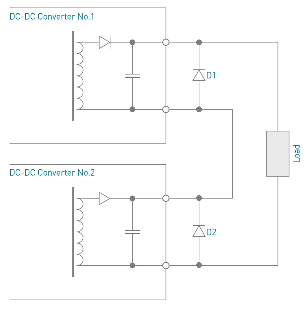
As shown in Figure 9, multiple isolated converters can be configured in series to achieve a higher total output voltage while maintaining electrical independence between modules. Commonly found in high-voltage testing equipment and specialized industrial power supply architectures.
Isolated converters can provide multiple independent output voltages within the same isolation structure, meeting diverse load requirements. For example, they can simultaneously power logic circuits, driver circuits, and communication modules, reducing the need for additional power modules.
Due to the floating ground at the output, designers can arbitrarily ground or float the output as needed to adapt to different system grounding strategies, such as differential amplifiers, sensor isolated power supplies, or systems spanning grounding networks.
Through transformer turns ratio design, both step-up and step-down functions can be achieved simultaneously. This is more flexible than non-isolated designs and suitable for applications requiring conversion across a wide voltage range, such as electric vehicle BMS, energy storage systems (ESS), and distributed power architectures (DPA).
Typical Application Areas for Isolated DC-DC Converters
- Industrial Systems
- Railway Systems
- Renewable Energy
- Medical Equipment
Widely used in PLCs, industrial automation controllers, motor drives, sensor networks, etc., responsible for power isolation and voltage conversion between different subsystems. The isolation design prevents high-voltage surges and electromagnetic interference (EMI) in the production environment from affecting control circuits, ensuring stable operation of multiple devices over long periods and improving system immunity and safety.
Suitable for signaling systems, train control systems, and onboard equipment in rail transit. Railway power supply environments are often accompanied by high-voltage transients, strong electromagnetic interference, and ground potential differences caused by long-distance transmission. Isolated DC-DC converters can establish safe isolation between different electrical sections, protecting the reliability of communication and control modules while meeting railway-specific standards such as EN 50155.
Used in solar inverters, wind turbine control systems, and energy storage devices (ESS) for voltage conversion and isolation between the generation and control ends. Isolation prevents high-voltage DC bus interference with low-voltage control circuits, improving system efficiency and safety, while complying with renewable energy safety standards such as IEC 62109.
Widely used in patient-contact instruments (such as monitors, electrocardiographs, infusion pumps, medical imaging equipment, etc.) to provide isolated power to high-precision measurement and signal processing modules, preventing leakage current or noise conduction to patients, and meeting the stringent requirements of IEC 60601-1 for isolation voltage and leakage current, ensuring the safety of patients and operators.
What Is a Non-Isolated DC-DC Converter? Topologies, Advantages, and Typical Use Cases
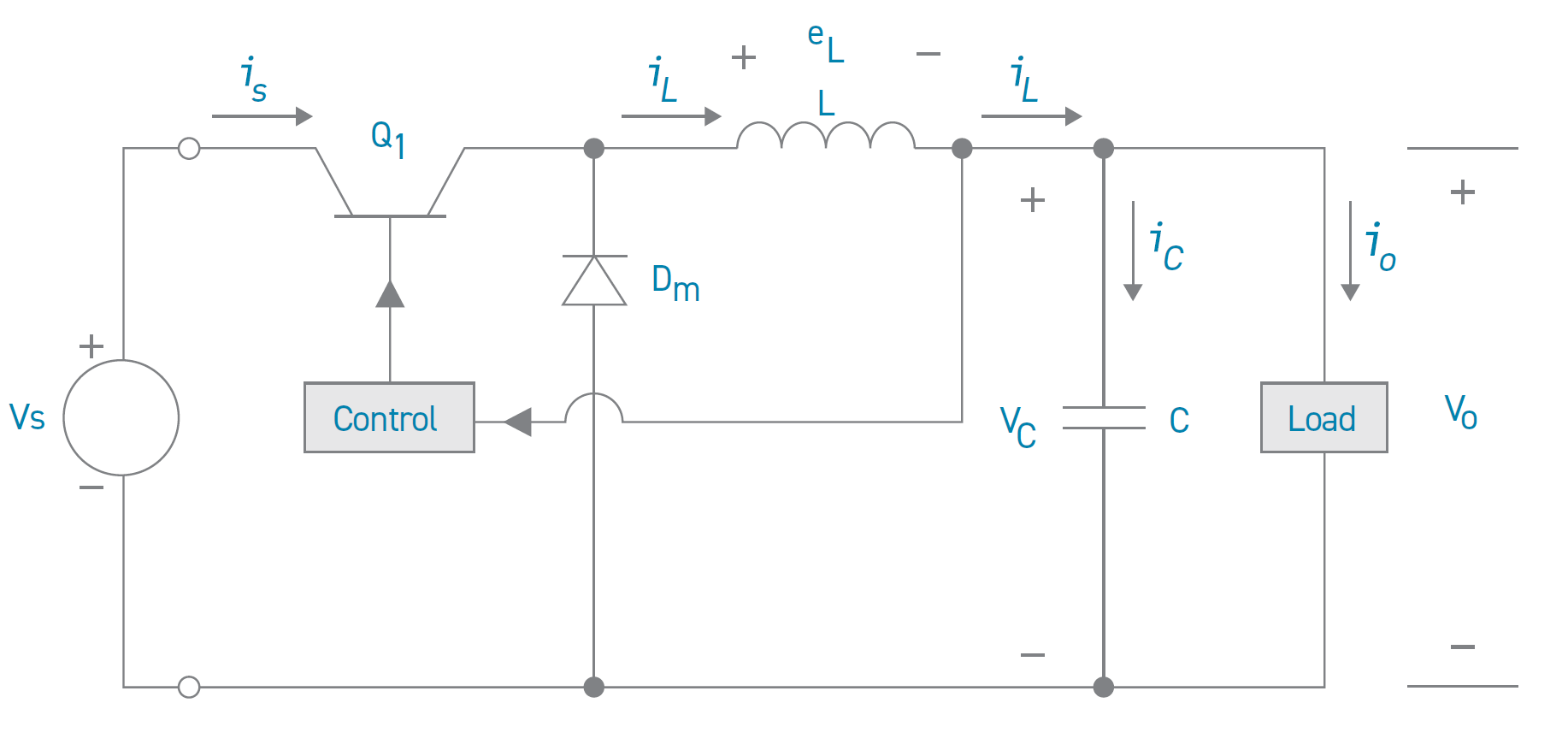
As shown in Figure 10, non-isolated DC-DC converters do not provide galvanic isolation. The input and output share the same electrical ground. Common topologies include Buck, Boost, and Buck-Boost converters, which are valued for their simple structure and high efficiency.
- 1. High Conversion Efficiency
- 2. Small Size
- 3. Low Cost
Because non-isolated DC-DC converters eliminate the need for transformers and related isolation components, they offer shorter power transmission paths and lower energy losses, typically achieving efficiencies of at least 90%. This is particularly important for battery-powered systems such as mobile devices, IoT nodes, and portable instruments, as higher efficiency translates to lower heat loss and longer battery life.
The simple structure and fewer components allow non-isolated designs to achieve higher power density at the same output power. For example, buck converters can be packaged in packages only a few millimeters square, making them suitable for space-constrained applications such as wearable devices, compact embedded systems, and automotive electronic modules.
Due to the elimination of transformers, high-voltage isolation materials, and complex insulation structures, non-isolated converters have significantly lower BOM and manufacturing costs than isolated solutions. This offers significant economic benefits for mass-produced consumer electronics and cost-sensitive applications such as smart appliances, LED lighting modules, and entry-level communication devices.
Common applications of non-isolated DC-DC converters include
Non-isolated DC-DC converters are widely used in low-voltage systems where compact size, high efficiency, and cost-effective power conversion are required. They are commonly found in consumer electronics, computing platforms, automotive electronics, and sensor-based systems that share a common ground.
- 1. Smartphones
- 2. Computers
- 3. Automotive
- 4. Sensors
In smartphones, non-isolated DC-DC converters (such as buck, boost, and buck-boost topologies) are used for battery power management (PMIC) and multi-rail regulation to ensure accurate and stable voltage for different modules (processor, display, wireless module, camera, etc.). Non-isolated designs achieve high efficiency and small size in such low-voltage, single-power-domain systems, extending battery life and reducing heat generation.
The CPUs, GPUs, memory, and chipsets of desktop computers, laptops, and servers are typically powered by non-isolated point-of-load (PoL) converters, which step down the mains power (such as 12V, 19V) to extremely low core voltages (such as below 1V). Non-isolated architectures provide high-current output with high efficiency and respond quickly to load changes, ensuring computing performance and stability.
In automotive electronics, non-isolated DC-DC converters are commonly used to step down 12V or 48V battery voltage to the operating voltages required by electronic control units (ECUs), infotainment systems, lighting modules, and ADAS sensors. Since most circuits in a vehicle share the same power system and have stringent requirements for efficiency, heat dissipation, and size, non-isolated designs offer a compact and efficient solution.
In the fields of Internet of Things (IoT), smart manufacturing, and industrial automation, sensor nodes are typically space-constrained, power-limited, and operate at voltages close to the system power supply. Non-isolated DC-DC converters can provide stable voltages in extremely small packages, support low-power modes, extend battery life, and maintain measurement accuracy and system stability.
Isolated vs. Non-Isolated DC-DC Converters: Key Differences
Understanding the differences between the two types of DC-DC converters is crucial for design decisions when choosing the appropriate type. The following are the main comparison items and technical specifications:
| Item | Isolated DC-DC Converter | Non-Isolated DC-DC Converter |
|---|---|---|
| Electrical Isolation & Safety |
Yes (Galvanic Isolation) — Provides an isolation barrier through a transformer or optocoupler, helping block noise transmission, eliminate ground loops, and improve system stability. |
No — Input and output share a common ground, so noise may propagate more easily and ground loop interference can occur. |
| Safety Protection | High — Prevents high voltage from reaching the secondary side and supports compliance with safety standards such as IEC 60601-1 and IEC 62368-1. | Low — Does not provide safety isolation and is generally suitable only for low-voltage power conversion within the same system. |
| Efficiency | Moderate to High — Additional transformers and insulation structures introduce extra losses, though modern designs can still achieve high efficiency. | Very High — Simple topology and shorter power path reduce losses, making high conversion efficiency easier to achieve. |
| Size | Larger — Requires transformer, insulation spacing, and safety-related design, so the overall size is usually bigger. | Smaller — Without transformer and isolation structure, the layout can be more compact and space-efficient. |
| Voltage Conversion Range | Wide — Transformer turns ratio enables flexible step-up or step-down conversion while maintaining electrical isolation. | Limited — Supports buck, boost, or buck-boost conversion, but usually within the same power domain and with a narrower conversion range. |
| Cost | Higher — Additional magnetic components, insulation materials, layout constraints, and certification requirements increase cost. | Lower — Simpler structure and fewer components help reduce BOM cost and manufacturing complexity. |
| Applications | Industrial, Medical, Railway — Commonly used in systems that require electrical isolation, high reliability, and regulatory compliance. | Consumer Electronics, POL Power — Commonly used in compact, low-voltage systems where efficiency, size, and cost are the main concerns. |
When to Choose an Isolated DC-DC Converter?
- Requires a safety boundary: Human-machine interface, different SELV/PELV areas, or regulatory requirements for basic/reinforced insulation.
- Uncertain ground or ground potential: System segmentation, long-distance transmission, or risks associated with ground potential differences.
- Sensitive to differential-mode and common-mode noise: Systems such as measurement, sensing, and communication interfaces require isolation to reduce DM/CM noise coupling.
- High-voltage or noise source at the front end: Establish primary/secondary electrical isolation boundaries at the front end, then perform power distribution (POL) at the back end.
When to Choose a Non-Isolated DC-DC Converter?
- Co-grounding, on-board power supply (POL): Stepping down from 12/24/48 V to multiple logic/core voltages.
- Targets are efficiency, power density, and cost: Limited space and no safety isolation requirements.
- Fast Multiple Outputs:Multiple low-power points; non-isolated step-down devices offer high efficiency and good transient response.
※Common System Architecture:Front-end "isolation" establishes safety and EMI boundaries → Back-end "non-isolation" enables multiple POLs. Using both approaches leverages their respective strengths.
Conclusion: Selection Guidelines and Common Power Architecture
The choice should be based on a comprehensive evaluation of factors such as application safety requirements, efficiency targets, cost budget, and voltage conversion range.
- Isolated converters are suitable for applications requiring isolation across high and low voltage systems, grounding networks, or meeting safety regulations. They provide excellent safety protection and interference immunity.
- Non-isolated converters are suitable for efficient voltage regulation within the same power domain, especially in space-constrained or cost-sensitive designs, balancing performance and size.
MINMAX Technology, as a leading designer and manufacturer of high-quality isolated and non-isolated DC-DC converters, delivers solutions that balance reliability, power density, and international safety certifications.
Most of our products feature isolated designs, with the MJWI40 and MKWI80 series being highly recommended for industrial control, medical equipment, and renewable energy applications. For space-limited and cost-sensitive designs without isolation requirements, the M78AR-1 series provides an optimal balance of efficiency, cost, and stable output.
Whether your application demands strict safety isolation or maximum power density and value, MINMAX offers proven, certified power conversion solutions to ensure safety, reliability, and competitive performance.