EN 50155:2017 Environmental Testing
Requirements for Operating Temperature
Railway applications often face challenging environmental conditions, such as high-altitude plateaus, hot and dry deserts, and cold and humid tundra. They may also be subjected to prolonged high temperatures in enclosed spaces or prolonged exposure to the elements alongside the tracks. Despite the unpredictable and ever-changing nature of surrounding railway environments, EN 50155 establishes stringent standards for measuring the operating temperature. This ensures that railway equipment continues to operate reliably under extreme environmental conditions.
EN 50155 is primarily divided into four categories to define different severe environmental conditions, as presented in Table 1 below. When designing a railway-certified DC-to-DC power module, it is crucial to consider whether temperature issues may arise during the system startup process.
Table 1 - Operating Temperature
| Level | Device Operating Temperature (℃) |
|---|---|
| OT1 | -25℃ to +55℃ |
| OT2 | -40℃ to +55℃ |
| OT3 | -25℃ to +70℃ |
| OT4 | -40℃ to +70℃ |
| OT5 | -25℃ to +85℃ |
| OT6 | -40℃ to +85℃ |
- OT1 and OT2 apply to passenger compartments and driver's cabins, where the long-term temperature must be maintained at +25℃. The temperature in these spaces may affect the lifespan of materials used.
- OT3 and OT4 should be applicable to equipment in cabinets, with a long-term reference temperature of +45℃. The ambient temperature in these spaces also affects the lifespan of materials used.
- OT5 and OT6 categories may not serve as a general specification for the vehicle temperature requirement (e.g., but may be applicable to semiconductor drive units (SDUs), engine control components, etc.).

Figure 1: Trains frequently operate in harsh climate conditions

Figure 2: Wide operating temperature range enables coping with severe climates
During the design process, it is necessary to consider the indoor temperature rise to ensure that components do not exceed their specified rated temperature. For instance, the ambient air temperature around the PCB may increase by approximately 15℃ (this temperature rise largely depends on the power consumption of the PCB itself and the adjacent PCBs, as well as natural or forced airflow). When designing the Printed Board Assembly (PBA), whether at a single PBA level or in a vertical stack or subrack configuration, the supplier should take into account the specific requirements arising from the particular onboard installation.
In certain exceptional circumstances, such as the influence of compartments, sunlight, or the closure of auxiliary cooling systems, additional operational checks on startup equipment under short-term hot conditions should be carried out according to ST1 or ST2 as outlined in Table 2 below.
Table 2 - Extended Operating Temperature - Startup State
| Level | Extended Operating Temperature - Startup State (Interval: 10 minutes) | Dry Heat Test |
|---|---|---|
| ST0 | No Extended Operating Temperature - Startup State | Cycle A |
| ST1 | OTx + 15℃ | Cycle B |
| ST2 | OTx + 15℃ | Cycle C |
※Levels ST1 and ST2 are not applicable to OT5 and OT6 as per Table 1.
※Unless otherwise specified, Level ST1 must be executed.
When trains pass through tunnels, the temperature often undergoes drastic changes. This significant temperature difference may lead to the formation of water droplets, moisture, and humidity, which have unforeseen effects on equipment. To address these issues, all MINMAX power modules are fully encapsulated to effectively resist the impact of external environmental factors. Furthermore, EN 50155 sets forth specifications for the expected performance of electronic devices in such environments. MINMAX's testing standards go beyond those defined by EN 50155, ensuring equivalent or even stricter testing conditions. For detailed information, please consult Table 3.
| Type of Test | EN 50155 : 2017(Source of Reference) / MINMAXTesting Level |
|---|---|
| A. Low Temperature Start-up Test |
EN 50155 13.4.4 / EN 60068-2-1
|
| B. Dry Heat Test |
EN 50155 13.4.5 / EN 60068-2-2
|
| C. Low Temperature Storage Test |
EN 50155 13.4.6 / EN 60068-2-1
|
| D. Cyclic Damp Heat Test |
EN 50155 13.4.7 / EN 60068-2-30
|
A. Low Temperature Start-up Test
To assess whether the product can start up properly at low temperatures, the testing will be conducted according to the low temperature levels specified in Table 1. The test procedure, as depicted in Figure 3, involves checking the functionality at room temperature before gradually lowering the temperature to the specified level. The stabilization period should last at least 2 hours. Subsequently, the equipment will be powered on for operational checks for 1 hour. Once the checks are completed, the equipment will be allowed to return to room temperature and remain at that temperature for 1 hour before undergoing another round of functionality checks upon restarting. Throughout the testing period and thereafter, the equipment can be deemed to have met Performance Standard A if it functions as expected and operates within its specified range.

Figure 3 A. Low Temperature Start-up Test
B. Dry Heat Test
To evaluate the performance of the product under high-temperature and dry heat conditions, the testing will be conducted using the high-temperature levels specified in Table 1 and the extended temperatures provided in Table 2, taking into account different external conditions. After selecting Cycle A/B/C, the corresponding test procedures are outlined in Figures 4/5/6. The stabilization period during the test should last for a minimum of 2 hours. If the equipment operates as expected and within its specified range both during and after the testing period, it can be deemed to have met Performance Standard A.

Figure 4. Dry Heat Test - Cycle A

Figure 5 Dry Heat Test - Cycle B

Figure 6 Dry Heat Test - Cycle C
C. Low Temperature Storage Test
To assess the product's ability to withstand low-temperature storage environments, the product will be placed in a test chamber without any power supply. The test temperature should be set to -40℃ and maintained for at least 16 hours. After returning to room temperature, functional verification will be performed. If the product operates normally within its specified range, it can be deemed to have met Performance Standard A.
D. Cyclic Damp Heat Test
The purpose of this test is to assess the product's ability to withstand variations in operating temperature and humidity. The test conditions are as follows:
- Temperature : +25℃ & +55℃
- Number of cycles : 2 cycles
- Duration : 2 x 24 hours
If the equipment operates as expected and within its specified range throughout the testing period and thereafter, it can be deemed to have met Performance Standard A.

Figure 7 Cyclic Damp Heat Test - Start of the 24-hour cycles for the first and second time

Figure 8 Cyclic Damp Heat Test - End of the second cycle and recovery period

Figure 9 Full encapsulation potting aids in the converter's resistance to external environmental factors
EN 50155:2017 Mechanical Testing
In the operation of high-speed trains, all equipment is subjected to continuous vibration, particularly as the speed continues to increase with technological advancements. However, along with these advancements come risks. Therefore, ensuring that equipment can withstand intense impact, vibration, and collisions while maintaining stable output or normal operation is a crucial concern for equipment manufacturers.
The EN 50155 certification explicitly states that the railway-grade DC-to-DC power converters installed on vehicles must meet the vibration and shock testing requirements of EN 61373. Therefore, strict control must implemented during the manufacturing process to ensure consistency in performance. MINMAX's railway-certified DC-to-DC power converters are specifically designed to meet high-impact and high-vibration tolerance, as well as to ensure stability and minimize the occurrence of faults during long-term operation, as per the EN 61373 vibration and shock standards.
Table 4 – Mechanical Testing
| Type of Testing | EN 50155 : 2017 (Source of Reference) | |
|---|---|---|
| Standard Testing Levels | Standard Testing Levels | |
| A. Functional Random Vibration Test | EN 50155 13.4.11.4 / EN 61373 (EN 60068-2-6) | |
| Category 1, Class B, Body Mounted Frequency Range: 5Hz~150Hz Grms Value: 0.103 Grms (1.01m/s²) for Vertical Axis Grms Value: 0.046 Grms (0.45m/s²) for Transverse Axis Grms Value: 0.071 Grms (0.70m/s²) for Longitudinal Axis Dwell Time: 10min/axis in Storage |
Category 1, Class B, Body Mounted Frequency Range: 5Hz~250Hz Grms Value: 0.2 Grms (2.0m/s²) for Each Axis Dwell Time: 10min/axis in Operation |
|
| B. Increased Random Vibration Test | EN 50155 13.4.11.2 / EN 61373 (EN 60068-2-6) | |
| Category 1, Class B, Body Mounted | Category 1, Class B, Body Mounted | |
| Frequency Range: 5Hz~150Hz | Frequency Range: 5Hz~250Hz | |
| Grms Value: 0.583 Grms (5.72m/s²) for Vertical Axis Grms Value: 0.260 Grms (2.55m/s²) for Transverse Axis Grms Value: 0.404 Grms (3.96m/s²) for Longitudinal Axis |
Grms Value: 1.2 Grms (12m/s²) for Each Axis Dwell Time: 5 HRs/axis in Operation |
|
| Dwell Time: 5 HRs/axis in Storage | ||
| C. Shock Test | EN 50155 13.4.11.3 / EN 61373 (EN 60068-2-27) | |
| Category 1, Class A&B, Body Mounted Wave Form: Half-Sine Acceleration Peak: 3.060 Grms (30m/s²) for Vertical Axis Acceleration Peak: 3.060 Grms (30m/s²) for Transverse Axis Acceleration Peak: 5.102 Grms (50m/s²) for Longitudinal Axis Dwell Time: 30mS in Storage Shock/Bump Times: 3 Times for Each Direction |
Category 3, Axle Mounted Wave Form: Half-Sine Acceleration Peak: 100 Grms (1000m/s²) for Each Axis Dwell Time: 6mS in Operation Shock Times: 3 Times for Each Direction |
|
| D. Bump Test | No Reference / No Reference (EN 60068-2-29) | |
| No Needed | Wave Form: Half-Sine | |
| Acceleration Peak: 5.102 Grms (50m/s²) for Each Axis | ||
| Dwell Time: 30mS in Operation | ||
| Acceleration Peak: 10 Grms (100m/s²) for Each Axis | ||
| Dwell Time: 11mS in Operation | ||
| Bump Times: 2000 Bumps for Each Direction | ||
A. Functional Random Vibration Test
First, we select the installation position of the testing equipment, which is divided into Body Mounting Class A, Body Mounting Class B, Bogie Mounting, and Axle Mounting. The equipment is then tested according to the related root mean square (RMS) values and frequency ranges given in Table 5. In cases where the actual direction of the equipment is uncertain or unknown, the test should be conducted with RMS values in the vertical direction on all three axes. Under the basic testing conditions of Body Mounting Class B, MINMAX increases the "vibration frequency" and "RMS acceleration" parameters to provide customers with greater reliability assurance.

Table 5 - Intensity and Frequency Range of Functional Random Vibration Test

Figure 10 - Horizontal Axis - Illustration of Functional Random Vibration Test Results (MINMAX Enhanced Version)
B. Increased Random Vibration Test
First, we select the installation position of the testing equipment, which is divided into Body Mounting Class A, Body Mounting Class B, Bogie Mounting, and Axle Mounting. The equipment is then tested according to the related root mean square (RMS) values and frequency ranges given in Table 6. In cases where the actual direction of the equipment is uncertain or unknown, the test should be conducted with RMS values in the vertical direction on all three axes. All types of equipment should undergo a total of 15 hours of testing, with 5 hours of testing conducted separately on each of the three mutually perpendicular axes.

Table 6 - Intensity and Frequency Range of Increased Random Vibration Test
")
Figure 11 - Horizontal Axis - Illustration of Increased Random Vibration Test Results (MINMAX Enhanced Version)
C. Shock Test
First, we select the installation position of the testing equipment, which is divided into Body Mounting Class A/B, Bogie Mounting, and Axle Mounting. The tested equipment is subjected to 18 shock impulses, with three tests each performed in the positive and negative directions of the horizontal, vertical, and longitudinal axes. Please refer to Table 7 for the test conditions.
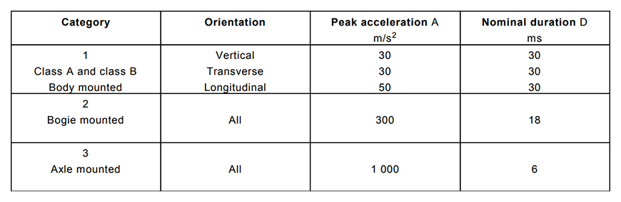
Table 7 - Directions, Intensity, and Duration of the Shock Test

Figure 12 - Positive Horizontal Axis - Shock Test (MINMAX Enhanced Version, 10Grms, 11ms)

Figure 13 - Positive Horizontal Axis - Shock Test (MINMAX Enhanced Version, 100Grms, 6ms)

Figure 14 - Ensuring Long-Term Reliability through Mechanical Testing
EN 45545-2 Fire Protection Testing
The railway transportation industry widely requires that power module materials meet the relevant requirements of fire protection testing specified in EN 45545-2. In the EN 45545-2 standard, different tested materials are classified and defined based on categories R1-R26, which specify the "fire performance parameters and test conditions."
Testing includes:
- Functional description of fire safety objects
- Grading and requirement levels for homogeneous materials
- Internal structural materials
The assessment of fire performance involves the following key parameters:
- Heat release rate
- Combustibility
- Toxicity testing
- Smoke density
- Different tested materials are evaluated for their fire protection testing level (HL Level) based on the final test results of the "fire performance parameter."
- In railway rolling stock, the fire protection testing level required for the materials used is determined based on the operating environment of the vehicle and the classification of different vehicle categories, as per classification table provided below (Table 4 - Hazard Classification).
Table 4 - Hazard Classification
| Operation category |
Design category | |||
|---|---|---|---|---|
| N: Standard vehicles |
A: Vehicles forming part of an automatic train having no emergency trained staff on board |
D: Double decked vehicles |
S: Sleeping and couchette vehicles |
|
| 1 | HL1 | HL1 | HL1 | HL2 |
| 2 | HL2 | HL2 | HL2 | HL2 |
| 3 | HL2 | HL2 | HL2 | HL3 |
| 4 | HL3 | HL3 | HL3 | HL3 |
MINMAX conducts fire protection testing on the plastic housing, printed circuit board (PCB), and potting compound for all its railway-certified power modules. These materials are tested based on the final "fire performance parameter" results to assess their fire protection level (HL Level) and ensure the safety of railway vehicle operations.

Application of Railway Vehicles
The requirements for railway equipment are adjusted based on different railway types, purposes, and installation positions. Please refer to Figure 15 for a further understanding of the typical equipment positions on railway vehicles:
1. Different Types of Railway Vehicles
Different types of railway vehicles, such as urban mass transit, underground transit, high-speed passenger trains, or freight trains, may lead to specific usage conditions.
2. Railway Vehicles with Different Purposes
The intended use of railway vehicles is influenced by geographical destinations and whether they operate underground or above ground. The specific conditions of the equipment may vary, depending on the intended purpose (e.g., the equipment mounting on bogies that are subjected to rapid temperature changes at the tunnel entrances/exits).
3. Equipment Positions on Railway Vehicles
Figure 15 illustrates the typical equipment positions on railway vehicles, such as Position 4 (underneath or on the roof of the vehicle), Position 5 (between vehicles), Position 6 (bogies), and Position 7 (axles), which are subjected to different conditions of use based on their design in different positions.
Table 5 provides an overview of the equipment positions and the corresponding requirements.
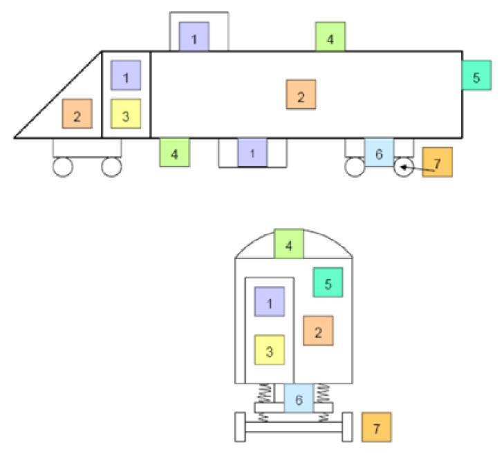
Table 5 - Examples of Typical Equipment Positions on Railway Vehicles
| Position | Definition | Definition | Expected Outcome |
|---|---|---|---|
| 1 | Enclosed electrical operator | Internal vehicle compartments (with wind and rain protection External vehicle compartments (with wind and rain protection) Under the frame or on the roof |
Working temperature and/or impact level depend on the installation position. |
| 2 | Driver's cabin and interior | Passenger compartments and driver's cabin | Only international protection certification with lower levels is required. (low dust and chemical pollution in the air) |
| 3 | Enclosed electrical operator with forced filtered fresh air ventilation | Mechanical compartment | Higher working temperature in the engine (or power converter) room or resistance to fuel and liquids. |
| 4 | Outdoor static application | Underbody, roof underside (non-weather-protected positions) |
|
| 5 | Outdoor dynamic application | Between vehicles |
|
| 6 | Outdoor high dynamic application | Bogie |
|
| 7 | Outdoor high dynamic application | Axle |
|
End of Why is it necessary for a power converter to comply with the EN 50155 railway certification? (Part 2)
Thank you for watching. If you are interested, please refer to the previous episode:"Why is it necessary for a power converter to comply with the EN 50155 railway certification? (Part 1)."
For more information, please click on the following links:
- [MINMAX Railway Certified Products _ Power Solutions]
- [MINMAX Railway Certified Products _ Product Selection Guidebook]
- [MINMAX Railway Certified Product _Product Introduction Video]
- [MINMAX Railway Certified Series _ Quarter Brick_MRZI150 Series]
- [MINMAX Railway Certified Series _ 2" x 1"_MKZI40 Series]
- [MINMAX Railway Certified Series _ DIP-24_MIZI03 Series]
