Robust Mechanical and Thermal Shock Design
The application environment of railways is highly variable, requiring consideration of multiple conditions such as climate, temperature, humidity, terrain, and power supply methods. In one hour, it could be scorching hot in a desert, while the next hour might be extremely cold in a frozen tundra. Therefore, the performance of power converters in harsh environments must be viewed from the most rigorous perspective. You can refer to the following standards:
- Low-temperature startup test : EN 50155 13.4.4 / EN 60068-2-1
- Dry heat test : EN 50155 13.4.5 / EN 60068-2-2
- Low-temperature storage test : EN 50155 13.4.6 / EN 60068-2-1
- Damp heat cyclic test : EN 50155 13.4.7 / EN 60068-2-30
- Functional random vibration test : EN 50155 13.4.11 / EN 61373 (EN 60068-2-6)
- Enhanced random vibration test : EN 50155 13.4.11 / EN 61373 (EN 60068-2-6)
- Shock test : EN 50155 13.4.11 / EN 61373 (EN 60068-2-27)
MINMAX's railway-certified products meet all the above test requirements, providing customers with the most reliable solutions in the face of harsh environmental conditions.

Figure 8: MINMAX provides durable, robust, and reliable railway-certified products
Passing Rigorous Temperature Cycling Tests
To verify long-term reliability, MINMAX's railway-certified products undergo temperature cycling tests of over 500 cycles. Within each cycle, the products must rapidly rise to a high temperature of +125°C and then descend to a low temperature of -40°C at a rate of 20°C per minute. This creates a temperature difference of up to 165°C. MINMAX adopts the most stringent testing approach to ensure that the products meet the demanding requirements of railway systems.

Figure 9: Passing temperature cycling tests of over 500 cycles
Operating at an Altitude of 5,000 Meters
To obtain necessary certifications, the specifications defined in IEC 62368-1 require compliance with operating conditions from sea level up to an altitude of 2,000 meters. However, this also means that equipment installed with these components can only be used within the altitude range of 2,000 meters.
Many cities in Europe, Asia, or the Americas are built at altitudes higher than 2,000 meters where the most modern electrical and electronic equipment markets exist. Europe is an example where many telecommunications base stations are placed at the highest possible locations to achieve maximum range and coverage. However, China has taken a step further in this field. For instance, the GB 4943.1-2011 standard already requires medical equipment to be suitable for applications at an altitude of 5,000 meters.
Therefore, MINMAX has subjected the majority of its railway-certified products to testing at an altitude of 5,000 meters. This helps to avoid short-circuiting issues caused by PCB track routing, air gaps, or arcing, thereby resolving the height limitations faced by railways operating at high altitudes.

Comprehensive Reliability Testing
In addition to EN 50155 certification, MINMAX's railway-certified products undergo even more careful and stringent testing to provide customers with high-quality and highly-reliable products.
| Type of Test | Test Conditions |
|---|---|
| Reliability Testing of Developing Products | |
| Burn-in | Input Line: Nom. Line Output Load: Full Load Temperature: Room Temperature Duration: 1032 HRs |
| Highly Accelerated Life Test(HALT) | Thermal Step Stress Test Rapid Thermal Stress Test Vibration Step Stress Test Combined Environmental Stress Test |
| Temperature Cycling Test(TCT) | Temperature Change: -40℃ ~ +125℃ Steady State Duration: 30min Ramp Rate: 20℃/min Number of Cycles: 200+ |
| Temperature & Humidity Storage Cycling Test (Non-Operation) |
Temperature Change: Low to High Temperature Ramp Rate: 1-3℃/min Relative Humidity: +95% RH. Steady State Duration: 1 HR Number of Cycles: 5 Cycles |
| Power and Temperature Cycling Test(PTCT) (In Operation) |
Input Line Change: Low/Nom./High Line Output Load Change: No or Min./Full Load Temperature Change: Low to High Temperature Relative Humidity: +95% RH. Duration for ON/OFF: 3 Sec Number of Cycles: 300 Cycles |
| Temperature, Humidity and Bias Test(THB) (In Operation) |
Input Line: High Line Output Load: No or Min. Load Temperature: +85℃ Relative Humidity: +85% RH. Operating Duration: 1000 HRs |
| Low Temperature Test (In Operation) |
Input Line: Nom. Line Output Load: Full Load Temperature: Low Temperature Duration: Achieve Thermal Equilibrium |
| High Temperature Test (In Operation) |
Input Line: Nom. Line Output Load: Full Load Temperature: High Temperature Duration: Achieve Thermal Equilibrium |
| Vibration Test(Non-Operation) | Waveform: Random |
| P.S.D Level: 10 Hz․1.04×10⁻³ g2/Hz 30 to 200Hz․20.8×10⁻³ g2/Hz 500 Hz․2.08×10⁻³ g2/Hz |
|
| Duration: 30 minutes | |
| Directions: X, Y and Z | |
| Shock Test(Operation) | Waveform: Half-sine Acceleration: 30 g Duration: 11 ms Number of Shocks: 3 shocks for each ±axis |
| ESD Test | Contact Discharge: ±4KV Air Discharge: ±2/4/8KV |
| Soldering Heat Test | MIL-STD-202F Method 210E |
| RoHS | RoHS Directive 2011/65/EU |
| Extra Testing | |
| Drop Test | Drop Height: 66 cm |
| Drop Sequence: 1 corner, 3 edges and 6 faces | |
MINMAX Green Energy Design
Higher Overall Conversion Efficiency
MINMAX's latest green energy design ensures that its railway-certified products maintain high conversion efficiency regardless of variations in output current, input voltage, or ambient temperatures. It also reduces the efficiency variation under different conditions to achieve energy savings, improved heat management, and addressing concerns related to temperature increase.

Figure 10: Efficiency vs. Load Curve
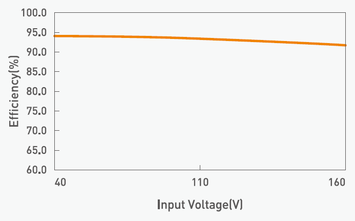
Figure 11: Efficiency vs. Input Voltage Curve

Figure 12: Efficiency vs. Operating Ambient Temperature Curve
Energy Savings and Addressing the Issue of Temperature Increase
By utilizing MINMAX's latest green energy design, the products achieve lower idle power consumption, which significantly improves the issue of temperature increase, mitigates heat management problems, and ultimately leads to energy savings and an extended operational lifespan of train batteries.

Figure 13: Power Consumption vs. Load Curve
No Minimum or Dummy Load Requirement
MINMAX's railway-certified power supplies feature an internally designed negative feedback circuit with high stability. This design ensures that the output voltage remains stable and does not generate resonance or oscillation even under conditions of no load or extremely light load. This contributes to the stability of the system during operation.

Faster Startup Time without Overvoltage
MINMAX's railway-certified products have a faster startup time without generating overvoltage. This feature helps to prevent system failures during load conditions and ensures safety during prolonged operation.

Figure 14: Rapid Startup Completed in just 20ms
Enhanced Load Driving Capability
MINMAX's MRZI150 series offers excellent system load driving capability even under extremely low or zero output voltage, ensuring successful startup without failures to meet the needs of onsite operation.

Figure 15: MRIZ150 series exhibits outstanding instantaneous load driving capability
Ripple and Noise Suppression Capability
With upgraded noise filtering technology, MINMAX's railway-certified products maintain low output ripple and noise across a wide range of input voltage, output current load, and operating ambient temperatures. This capability allows our customer's system to reduce the need for external components and minimizes noise interference.

Comprehensive Fault Protection and External Control Features
MINMAX's railway-certified products come with comprehensive fault protection features, including input undervoltage protection, output overcurrent protection, output short circuit protection, output overvoltage protection, and over-temperature protection. Additionally, they are equipped with remote control switch functionality, output voltage fine-tuning capability, and sensing functionality. The fine-tuning feature allows adjusting the output voltage level, enhancing customer flexibility and freedom in system design.

Figure 16: Comprehensive fault protection is an essential safety feature in railway-certified products
Fully Encapsulated Vacuum Packaging for Protection from External Interference
MINMAX's railway-certified products are all wrapped in fully encapsulated vacuum packaging, providing excellent protection and resistance against environmental electromagnetic interference (e.g., static electricity) as well as environmental physical stress interference (e.g., thermal shock, temperature cycling, vibration, shock, impact, dust, moisture, oil, and gas). This packaging ensures comprehensive protection and resilience against various external disturbances.

Figure 17: Fully encapsulated vacuum packaging effectively blocks external interference
Passing Fire Protection Tests to Ensure Customer System Safety
All MINMAX railway-certified products undergo testing for four fire performance parameters: heat release rate, combustibility, smoke toxicity, and smoke opacity. These tests are conducted on the plastic casing, printed circuit board (PCB), and encapsulation materials of the products to ensure safety during railway operations.

Certified by International Accreditations
All MINMAX railway-certified products have undergone third-party certifications by international organizations or associations. These certifications not only demonstrate MINMAX's confidence in its products, but also provide customers with the assurance of using our products with peace of mind. By obtaining objective third-party certifications, we aim to eliminate any concerns regarding the safety or fairness of MINMAX's products.
- Railway Application : EN 50155 (IEC 60571)
- Fire protection on railway vehicles : EN 45545-2
- Vibration and shock testing: EN 61373
- Cooling, Drying, Damp Heat Reliability Test Standards
- Damp heat compliance testing : IEC/EN 60068-2-1, 2, 30
- Electromagnetic compatibility (EMC): EN 50121-3-2
- CE Label
- International standard for infotech equipment safety
- UL/cUL/IEC/EN 62368-1(60950-1)

End of Isolated DC-DC Power Converters for Railway Certification: An In-depth Analysis of Uncompromising Performance (Part 2)
Thank you for watching. If you are interested, please refer to the previous episode: An In-depth Analysis of Uncompromising Performance (Part 1)
For more information, please click on the following links:
- 【MINMAX Railway Certified Products _ Power Solutions】
- 【MINMAX Railway Certified Products _ Product Selection Guidebook】
- 【MINMAX Railway Certified Product _Product Introduction Video】
- 【MINMAX Railway Certified Series _ Quarter Brick_MRZI150 Series】
- 【MINMAX Railway Certified Series _ 2" x 1"_MKZI40 Series】
- 【MINMAX Railway Certified Series _ DIP-24_MIZI03 Series】
